
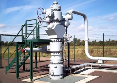
Wellhead Equipment and Christmas Tree
Throughout the entire oil & gas production chain, a piece of equipment is known as the “throat of of the wellhead”-it not only bears the weight of the tubing string, but also precisely controls oil & gas production, and maintains safety in emergencies. This equipment is the wellhead assembly and the Christmas tree.
Simply put, the wellhead assembly is a “family of equipment” consisting three core components:
The Christmas tree: the “spindle” that controls oil & gas production,
The tubing head: the “bridge” connecting the tubing and casing,
The casing head: the “foundation” that secures the casing and seals the annulus.
Combined with valves, flanges, and other accessories, these components fullfill four fundamental functions: suspension, support, control and sealing, directly determining the safe and efficient production of oil & gas wells.
1, Wellhead assembly: all the fixed equipment between the top of the surfacing casing and the tubing head, it is the “skeleton” of the wellhead.
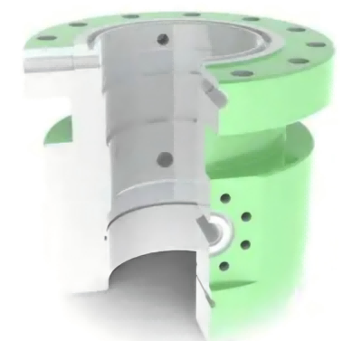
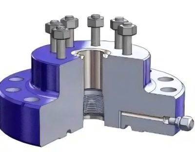
2, Casing head housing: A component connected to the top of the surfacing casing, specially designed to hang the casing string.
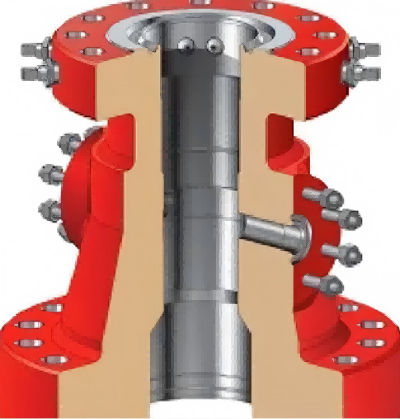
3, Tubing-head spool: connects the casing head and the Christmas tree, it can not only hang the tubing but also seal the annular space between casing and tubing.
4, Mandrel-type hanger:A mandrel similar to a solid rod, is used to hang the casing in the well.
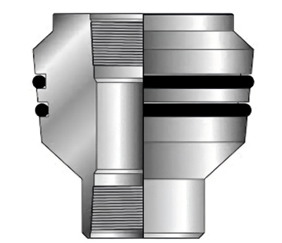
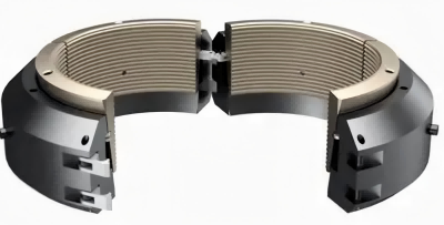
5, Slip-type hanger: It clamps the casing tightly with a wedge-shaped clamp and hangs the casing string like a clip. It is quick to be installed and with strong adaptability.
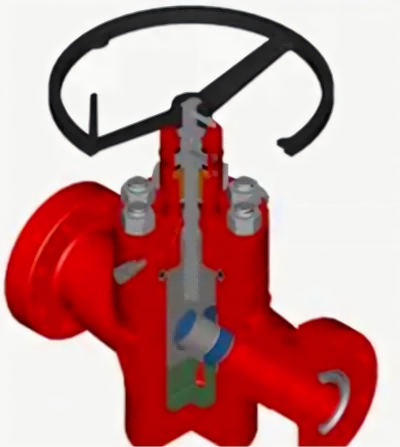
6, Gate valve: A type of valve that relies on a valve plate that can move vertically up and down along the axis of the pipeline passage to cut off oil and gas. It is the most commonly used “switch” at the wellhead.
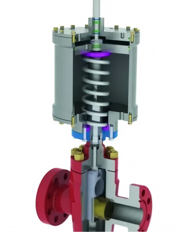
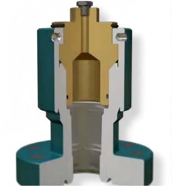
7, Surface safety valve:“safety guard”-once the power is lost(such as power outage or gas cut-off), it will automatically close to prevent leakage.
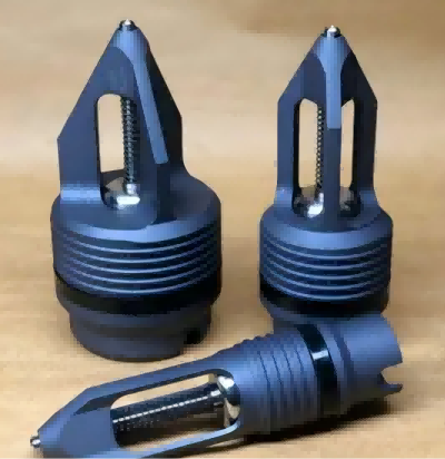
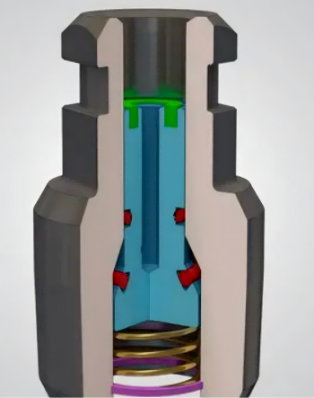
8, Choke valve: It controls the flow and pressure of oil & gas by adjusting the hole diameter, functioning as the “throttle” at the wellhead.

9, Back-pressure valve: A one-way/two-way check valve that serves as “temporary gatekeeper” to prevent well fluid from leaking out during maintenance.
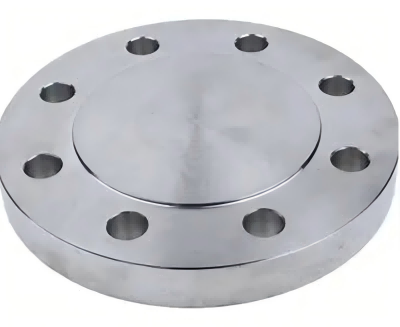
10, Blind flange: A flange without a through hole, used to seal the excess joint at the wellhead to prevent debris from entering.
11, VR plug(valve-removal plug): A special threaded plug that enables the gate valve to be removed under pressure without the need to stop the well.
12, Top connector: The topmost connector of the Christmas tree, it can connect the equipment above with the “vertical hole” that runs through the middle of the Christmas tree.
13, Tubing-head adapter: One end is connected to the tubing head, and the other end to the Christmas tree. It is specially designed to solve the problem that the interface size at the top of the tubing head does not match the valve size at the bottom of the Christmas tree, allowing the two devices to be smoothly connected.
Core functions of the wellhead assembly
1, Suspension and load-bearing: Acting like a “shoulder”, it supports casing, tubing, and down-hole tools, while also sealing the annular space between the casing and tubing to prevent fluid leakage from different layers.
2, Production control: Regulating oil&gas output through a throttle valve ensures production demand while preventing accidents caused by sudden drops in well pressure.
3, Operation support: Providing a channel for operations such as killing the well, acid fracturing, and tripping the tubing string, allowing operations to be completed without dismantling the equipment.
4, Date collection: Connecting to a pressure gauge allows real-time monitoring of oil and casing pressures, providing data support for production control.
5, Safety protection: surface safety valves, check valves, and other components automatically activate in the event of abnormal pressure or power outage, safe-guarding wellhead safety.
Installation steps of the wellhead assembly
1, First opening: Drill the guide pipe well-bore, insert the guide pipe, cementing the well, laying the first foundation of the wellhead.
2, Second drilling: Drill the surface casing well-bore, lower the surface casing, install the casing head, cementing and secure the the surface casing.
3, Third opening: Drill the technical casing well-bore, lower the technical casing, install intermediate casing head spool, conduct pressure testing to enhance the wellhead’s pressure-bearing capacity.
4, Fourth-round: Drill the oil layer casing well-bore, lower the oil casing, install the mandrel hanger, conduct a pressure test to prepare for oil production.
5, Install the tubing head spool, install the anti-wear sleeve, lower the tubing, install the hanger, conduct a pressure test and connect the tubing to the casing.
6, Install the Christmas tree, Install the back pressure valve, hoist the Christmas tree, conduct an overall pressure test, remove the back pressure valve to complete the wellhead assembly.